Monitor the voltage of a battery or battery bank using an TL431 (aka LM431) shunt regulator
With very sharp turn-on characteristics, the TL431 is an excellent alternative to a zener diode in many applications. In this article we will look at how a TL431 can be used to make a very simple battery status monitor.
Click here to view our article on making a battery status monitor with a zener diode.
The full National Semiconductor LM431 Datasheet (PDF) can be viewed by clicking here.
Note that the TL431 is also often labelled as a LM431 and may also be described as a programmable voltage reference.
Using the TL431
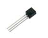
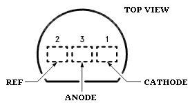
The TL431 is most commonly found in the TO-92 packaging pictured at the start of the article - a piece of black plastic out of which emerge three legs. Below the connections are labelled - REFis the voltage reference.
..and here below is shown the way the TL431 is represented in circuit diagrams

TL431s can be purchased cheaply from almost any stockist of electronic components worldwide. We also have them available for sale in the REUK Shop.
TL431 Voltage Monitor Circuit
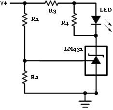
Above is shown the circuit diagram for this TL431-based voltage monitor. The aim of the monitor is simply to light up an LED when a target voltage is reached - perfect for a solar battery charger to let you know when the batteries have reached full charge.
The simple equation displayed above gives the high limit - in this case the voltage at which the LED will light up. Since the reference voltage (Vref) is fixed at 2.5 Volts in the TL431, the two resistors are simply selected to provide the desired result.
For example, if you require the LED to light up when the input voltage reaches 7 volts, R1 could be set to 1K8 (1,800 Ohms) and R2 to 1K. Multiplying 2.5 by (1+ (1800/1000)) gives 7.0 Volts exactly as required.
Ideally the R1 and R2 resistors used should both be well over 1K Ohm to ensure that the reference input current stays below its 10mA safe use limit.
The resistor labelled R4 in parallel with the LED prevents the LED from glowing softly when the input voltage is still below the switch-on voltage. We used a 1K Ohm resistor in our experiments successfully. (The lower the resistance value used for R4 for sharper the switch-on
The R3 resistor is there to protect the LED from excessive current - we used a 500 Ohm resistor, but the value selected depends on the specification of the LED used and the brightness required.
- i.e. a tiny increase in voltage causes the LED to suddenly light up brightly).
Testing the Voltage Tester
Below is a photograph of a voltage monitor put together on prototyping breadboard using the LM431 to light up an LED when a voltage of 6.25V is reached.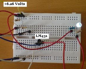
A 1K5 and a 1K resistor were used as R1 and R2 respectively to achieve the desired 6.25 Volts limit. A variable voltage source was then used to test the circuit. When the input voltage was 6.26 Volts the LED lit up (as shown above), and when the input voltage fell to 6.25 Volts the LED switched off completely (as shown below).
http://www.reuk.co.uk/TL431-Battery-Voltage-Monitor.htm