Build an electronic pump controller for a solar water heating system
Any solar water heating system (DIY or otherwise) with a pump must have an electronic controller of some sort if everything is to run optimally.
Solar Water Heating Controller
This controller detects the temperature of the solar panel as well as that of the tank which stores the heated water. Whenever the solar panel is hotter than the stored water, the pump should run to send hot water from the panel into the hot water tank. However, when the stored water is hotter than the solar panel, the pump (pictured below) should be off since the stored water would otherwise be cooled by the panel.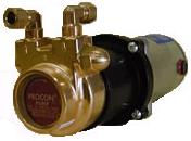
Since this is a very simple concept, it is possible for anyone to build their own solar water heating pump controller relatively easily, and very cheaply. 12V 5 Watt pumps are available which can be powered directly by similarly rated PV Solar Panels providing completely renewable energy water heating.
Solar Water Heating System Pump Controller Circuit
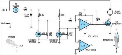
The circuit diagram displayed above is from the Silicon Chip Online article entitled Pump Controller for Solar Water System. (Click on the circuit diagram to view a larger printable version).
This very simple circuit is made up of just a few components. Key are the two temperature sensors (LM335Z) which are used to measure the temperatures of the solar panel and the water tank, and the comparator chip (LM393) which compares the two temperature readings. An STP60NE06 mosfet (a type of transistor) is used to turn on the pump when triggered by the output from the comparator.
When the temperature of Sensor 1 (solar panel) is higher than the temperature of Sensor 212V solar water pump is activated pumping hot water from the solar panel to the water tank as desired. When the temperature of the water tank is higher than that of the solar panel (for example at night) the pump is off.
(water tank), the
LM335Z Temperature Sensors
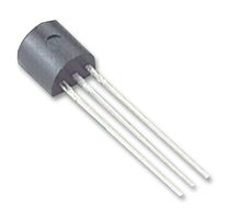
The voltage measured between the ground and the positive terminals of the LM335Z increases at 10mV per °C. Since absolute zero is -273°C, at 0°C, the voltage measured at 0°C is 2.73V . At room temperature the voltage will be 273 + 20 = 2.93 Volts etc.
Since every sensor is slightly different, the circuit includes a couple of 10k variable resistors
which can be used to set the voltage output of the two sensors used so that they give exactly the same reading when they are at the same temperature.
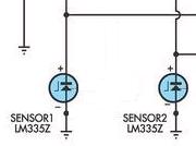
Since the sensors are accurate to within 1°C, the variable resistors (trimpots) can be left out to simplify the circuit as shown above. Put the sensor with the higher output voltage at a particular temperature as Sensor 2 so that if both sensors are at the same temperature, the pump will be off.
Sensor 1 should be stuck against the copper pipe as it leaves the solar panel, and Sensor 2Note that water + sensor = broken sensor)
should be connected to the outside of the hot water tank underneath the insulation. In this way the two sensors will measure the temperature of the water pretty accurately without getting themselves wet. (
Putting the Controller Together
Pictured below is the complete circuit put together for testing on prototyping breadboard .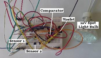
For testing purposes the two temperature sensors have been placed side by side on the breadboard, and a 12V LED Spotlight Bulb is used instead of the hot water pump.
Since the two temperature sensors are at the same temperature the pump is off. The 1 MOhm resistor across legs 1 and 3 of the comparator chip provides 12mV of hysteresis - i.e. the readings from Sensor 1 and Sensor 2 have to differ by at least 12mV (1.2°C) for the output from the comparator chip to be changed.
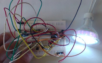
When Sensor 1 (solar panel) is warmed up slightly by the heat of a finger, the light bulb used in this prototype turns on as it should.
Modifying the Pump Controller Circuit for 240 VAC pump
If the hot water pump is a 220-240 Volt AC model (or 120 VAC for US visitors), then this same circuit can still be used by using a 12V relay (and diode) in place of the 12V pump in the circuit. When the temperature of the solar panel sensor is higher than that of the hot water tank, the relay will be triggered supplying electricity (from an external 240 Volt AC source) to the hot water pump.Buying the Controller Components
If you are interested in building your own pump controller and you need to buy some or all of the necessary components, contact us and we will put together a package for you from the REUK Shop.http://www.reuk.co.uk/Solar-Water-Heating-Pump-Controller.htm