Saturday, June 30, 2007

What is a Transistor

A basic introduction to bipolar junction transistors

A Transistor is an semiconductor which is a fundamental component in almost all electronic devices. Transistors are often said to be the most significant invention of the 20th Century. Transistors have many uses including switching, voltage/current regulation, and amplification - all of which are useful in renewable energy applications.

A transistor controls a large electrical output signal with changes to a small input signal. This is analogous to the small amount of effort required to open a tap (faucet) to release a large flow of water. Since a large amount of current can be controlled by a small amount of current, a transistor acts as an amplifier.

A transistor acts as a switch which can open and close many times per second.

Bipolar Junction Transistors

The most common type of transistor is a bipolar junction transistor. This is made up of three layers of a semi-conductor material in a sandwich. In one configuration the outer two layers have extra electrons, and the middle layer has electrons missing (holes). In the other configuration the two outer layers have the holes and the middle layer has the extra electrons.
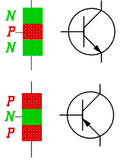
NPN and PNP transistor schematics

Layers with extra electrons are called N-Type, those with electrons missing called P-Type. Therefore the bipolar junction transistors are more commonly known as PNP transistors and NPN transistors respectively.

Bipolar junction transistors are typically made of silicon and so they are very cheap to produce and purchase.

How do Transistors Work
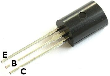
Bipolar junction transistor with labelled inputs

A bipolar junction transistor has three terminals - Base, Collector, and Emitter
corresponding to the three semi-conductor layers of the transistor. The weak input current is applied to the inner (base) layer. When there is a small change in the current or voltage at the inner semiconductor layer (base), a rapid and far larger change in current takes place throughout the whole transistor.
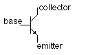
Schematic of an NPN transistor
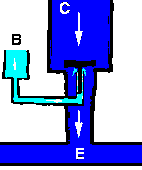
Pictured above is a schematic diagram of the more common NPN transistor. Below is an illustration of the same transistor using water rather than electricity to illustrate the way it functions:

Transistor water analogy

The illustration (from satcure-focus.com) shows pipework with three openings B (Base), CE (Emitter). The reservoir of water at C is the supply voltage which is prevented from getting though to E by a plunger. If water is poured into B, it pushes up the plunger letting lots of water flow from C to E. If even more water is poured into B, the plunger moves higher, and the flow of water from C to E increases.

Therefore, a small input current of electricity to the Base leads to a large flow of electricity from the Collector to the Emitter.

(Collector), and

Transistor Gain

Looking at the water analogy again, if it takes 1 litre of water per minute poured into B to control 100 litres of water per minute flowing from C to E, then the Gain (or amplification factor) is 100. A real transistor with a gain of 100 can control 100mA of current from C to E with an input current of just 1mA to the base (B).

If the output power (current x voltage) are more than 1 Watt a Power Transistor must be used. These let much more power flow through, and require a larger controlling input current.

Simple Transistor Circuit
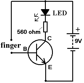

Very simple transistor circuit

Pictured above is a very simple circuit which demonstrates the use of transistors. When a finger is placed in the circuit where shown, a tiny current of around 0.1mA flows (assuming a finger resistance of 50,000 Ohms). This is nowhere near enough to light the LED which needs at least 10mA. However the tiny current is applied to the Base of the transistor where it is boosted by a factor (gain) of around 100 times and the LED lights!


http://www.reuk.co.uk/What-is-a-Transistor.htm

Sturmey Archer Dynohub

The Sturney Archer Dynohub in RE Applications

A simple way to learn more about building wind turbine generators is to use a bottle dynamo or Sturmey-Archer Dynohub as your alternator rather than building your own. While bottle dynamo generators are useful, they suffer from large friction losses and do not generate much power, therefore the Dynohub is of more interest. It generates power at a much lower RPM (60 RPM to generate 6V / 3W) than a bottle dynamo which is useful for a practical wind turbine.

What is a Dynohub

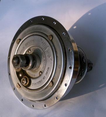
The Sturmey Archer Dynohub is a heavy over-sized hub that fits onto a bicycle and generates AC electricity with no moving parts of mechanical frictional losses. As the wheel of the bicycle turns, a ring-shaped 20-pole magnet revolves around a fixed coil attacted to the wheel axle. Used in its traditional sense the Dynohub had a tendency to burn through bulbs when the cyclist raced down a hill since the voltage generated increased with the speed of rotation of the wheels.

Sturmey-Archer 6 Volt / 3 Watt Dynohub


Making a Dynohub Wind Turbine

Converting a Dynohub into a wind turbine generator is simply a matter of bolting on three suitable turbine blades. We recommend that you make your own PVC wind turbine blades

You will need to make the turbine blades at least 3 feet long (and ideally 4 feet long) since the Dynohub needs a good bit of torque to get it spinning. Blades any longer than 4 feet will turn the generator more slowly and put extra stress on the hub bearings.

since they are very cheap and easy to make.

Using a Dynohub Wind Turbine as a Battery Charger

As stated above, the electricity generated by a Dynohub is alternative current (AC). If you intend to connect your Dynohub wind turbine to a small incandescent light bulb you will have no problems - if the wind is strong enough to turn the turbine, the bulb will glow. If you intend to connect it to an LED then there will be some flickering since the LED will only light when the current flows in the correct direction. If however you intend to use your Dynohub as a batteryrectify the AC electricity output into direct current (DC) using a suitable bridge rectifier.

charger you will need to
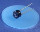
1.5 Amp 50 Volt Bridge Rectifier for use in a Dynohub Wind Turbine Generator Battery Charger

Pictured above is a W1005 1.5A 50V Bridge Rectifier perfect for use with a Dynohub wind turbine generator. We have these rectifiers for sale in our REUK Shop together with 35A Bridge Rectifiers (from £1.79) which are suitable for larger wind turbine generators.

A Smoothing capacitor should also be used to smooth the output from the bridge rectifiers if it is to be used to directly power an LED to prevent it from flickering on and off repeatedly. Suitable 16V 1,000uF capacitors are also available in the REUK Shop.

Buying a Dynohub

It is virtually impossible to find a Dynohub in the shops today - rather than a cycling shop you're better off looking in an antique shop! However they can occasionally be picked up on eBay in various conditions and ages from £15-£30 including postage, or found in scrap yards or on old bicycles.

22.01.07 Update: A suitable Dynohub is currently listed on ebay as item number 320109082687. UK P&P is £7 and the starting bid is just 99p. Don't miss out - the listing finishes on 06-May-07 17:19:56 BST.

Modern Alternatives to Sturmey Archer Dynohubs

If you are having a lot of difficulty obtaining a Sturmey Archer Dynohub then have a look for one of these alternative Dynamo Hubs for Wind Turbines.

Useful Dynohub Wind Turbine Links

Instructions on dismantling and servicing the Dynohub are available here. Or you can download an exploded drawing of a Dynohub here.

Here is a website which demonstrates the use of a 6Volt / 5Watt Dynohub clone in a working wind turbine generator: GotWind.org


http://www.reuk.co.uk/Sturmey-Archer-Dynohub.htm

DC Voltage Multiplier Circuit Plans

A DC voltage booster, DC voltage multiplier, or DC-DC Step-Up Converter is a very useful tool which enables a low source DC voltage to be boosted (stepped up) to a higher output DC voltage which is more useful.

For example, ultrabright LEDs need a 2.5-3.5 Volts to light: even two AA rechargeable batteries in series (1.2 + 1.2 = 2.4V) would not provide sufficient voltage to light up LEDs. Using a voltage boost circuit an LED can be powered by just one AA battery or any other power source - sometimes down 0.7 Volts!

This circuit can be used with low voltage solar panels to make a small battery charger or to power a 5 Volt device directly. It is also particularly good for getting useable voltages from small DIY stepper motor wind turbines - again to charge batteries or light LEDs.

The MintyBoost


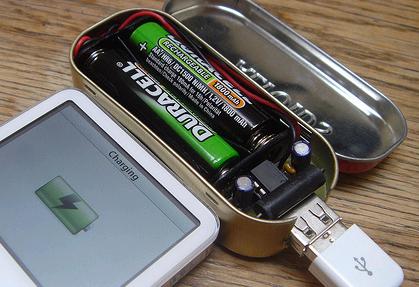
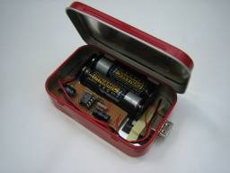
MintyBoost Small USB Battery Powered Charger

The origin of the booster circuit described in this article is the Original MintyBoost - a DIY device to power / recharge any USB device (e.g. an iPod) using just two rechargeable AA batteries. MintyBoost kits are available for sale ($19.50 in USA), however the circuit can be made with easy to find electronic components together with a MAX756 integrated circuit chip and put to alternative uses.

There is a useful forum where you can ask questions regarding the MintyBoost.

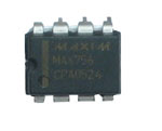
MAX756 3.3V/5V Step-Up DC-DC Converter

MAX756 Step-Up DC-DC Converter
The key component in this voltage booster is the MAX756 - an integrated circuit from MAXIM0.7 Volts to an ouput of 3.3 or 5 Volts87% efficiency. The maximum output current is 200mA which is sufficient for a wide range of applications including LED lighting, and the low minimum voltage input enables the full capacity of batteries to be used up.

The full MAX756 Specification Sheet (PDF 120K) is available for download here.

. This tiny chip boosts input supply voltages as low as (user selectable) at up to

Making the DC-DC Converter

The following parts are necessary to make this 0.7 to 5 Volt DC boost converter together with leads and either prototyping breadboard or soldering equipment and a board:

1 x MAX756
2 x 100uF Capacitors
2 x 0.1uF Capactitors
1 x 1N5817 Schottky Diode
1 x 22uH Power Inductor

The MAX756 is available direct from MAXIM with prices ranging from $3.02 (ordering 1-24) down to $1.95 (ordering 1000+). We can supply the rest of the components through the REUK Shop if required - email us to request a quote listing the components and quantities you require.

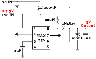
Circuit Diagram


Circuit diagram for 0.7 to 5V DC-DC converter

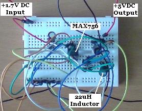
Pictured below is the (not very photogenic) finshed prototype circuit.

Completed MAX756 DC-DC Voltage Converter Circuit

The above circuit was tested using two 'flat' AA rechargeable batteries. The total voltage of the batteries was measured at 2.21 Volts, and the output voltage from the circuit was measured at exactly 5.00 Volts with a digital multimeter. The output voltage was used to power an ultrabright LED for 24 hours (through a 270 Ohm current limiting resistor) without any sign of dimming during that time.

3.3V Output from MAXC756

The circuit above is used to boost DC voltages from 0.7+ Volts up to 5.0 Volts. By changing the input to pin 2 of the MAX756 from ground to positive, the output is switched to 3.3 Volts. This enables some LEDs to be lit without needing a series resistor or with a smaller resistor, so there is less power wasted as heat.
The 3.3 Volt DC output can also be used to slowly charge a couple of AA batteries (in series) with the sub-200mA current output from the MAX756.

Alternative Circuit


Alternative DC-DC Converter using LT1073

Details of an alternative, but similar, USB Battery Pack circuit are available by clicking here. As with the MintyBoost, it is designed to power USB devices with the output from a couple of AA batteries however the circuit can be put to many other uses.

Instead of the MAX756, an LT1073 (specification sheet (1.4MB) here) integrated circuit is used. This chip is designed to be used in single-cell to 5V converters.


http://www.reuk.co.uk/DC-Voltage-Multiplier-Circuit-Plans.htm

Thursday, June 28, 2007

Battery System Monitor

Find out how to monitor your renewable energy system battery bank


Once you get beyond the simplest renewable energy system, it is necessary to include some battery bank monitoring equipment. Batteries are one of the most expensive and fragile components of a renewable energy system, and so it is essential that their status is carefully monitored. It is also very useful to track the charge coming in from the various sources in a combined system - usually photovoltaic solar panels and wind turbine generators - in order to see from where you are getting power.

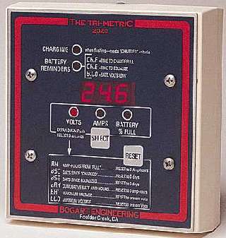
Probably the best known battery system monitor is the Bogart Engineering Tri-Metric 2020 Battery System Monitor. This device displays battery voltage, amps, amp-hours, battery percent full, and five other data functions, and works with systems from 12V to 48V for around £100. Great value as it costs the same as one decent battery and should increase the lifetime of your batteries:

The Tri-Metric 2020 Battery System Monitor from Bogart Engineering


Bogart Engineering have now introduced the new PentaMetric Battery Monitor which offers even more capability than the TriMetric.

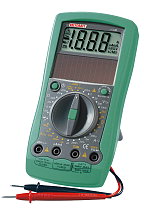
Another alternative if you are on a limited budget is a simple digital multimeter. Available from just £5, a digital multimeter can be used to measure the voltage of your battery bank, and the current (amps) being put into or drawn from the batteries when being charged or under load.

Germanium Diodes

Learn about the advantages of Germanium Diodes

Diodes are a very important component of most alternative energy generating systems - for example in PV solar panels they are used to stop energy being radiated back out into the night sky from the batteries, and in wind turbine generators they are used to rectify AC into DC electricity.

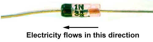
1N34A Germanium Diode


Typical diodes are made of silicon because of its ease of processing and stability however they have one disadvantage: a silicon diode has a forward voltage drop of around 0.7 volts. Therefore in a Bridge Rectifier where the current passes through two diodes, the total forward voltage drop is 1.4 volts. This is very significant in low voltage systems. A Germanium Diode typically will have a forward voltage drop of 0.3 volts which means they are much more efficient. Older germanium diodes had a larger leakage of current at a reverse voltage, but now American Microsemiconductor supply a range of improved low leakage current germanium diodes. Diodes such as the most common 1N34A cost around 5 pence each.

An interesting article about the practical use of Germanium Diodes in a crystal radio set is here, and discusses the forward voltage drop of a selection of germanium diodes in real world testing. The OA47 came out tops with a forward voltage drop of under 250mV.

http://www.reuk.co.uk/Germanium-Diodes.htm

Shunt Regulator

Find out about the uses of shunt regulators with alternative energy

A Shunt Regulator is a small electronic component that clamps a power supply voltage at a fixed level. Hundreds of times per second it checks the power supply voltage, and if the voltage is over the limit (set by adding a couple of resistors to the regulator in a small circuit) then the extra voltage is bled off through a resistor. If the voltage is below the fixed maximum, then no current passes through the resistor.

How can shunt regulators be useful to alternative energy generators. Well, for example a solar panel rated at 12V will actually generate up to 20V. If this panel is to be connected directly to equipment requiring an input of 12V, that equipment could be damaged if the voltage is too high. Therefore, by passing the solar panel's generated current through a shunt regulator circuit, the voltage reaching the equipment can be clamped at 12V very accurately.

Rather than dumping the excess power into a resistor and losing it in the form of dissipated heat, it is possible to put it to better use, for example to heat or pump water.

A common shunt regulator used in solar applications is the LM431. This is a 3-terminal adjustable shunt regulator which can have its output voltage set to any value between 2.5 and 36V by the correct selection of two resistors. LM431's are available for example from eBay at just $4.50 for 25.

http://www.reuk.co.uk/Shunt-Regulator.htm

Fuse And Solar Panels

Using a fuse to prevent a short when connecting solar panel to battery

It is essential to fuse the wiring between a solar panel set up and the battery bank for safety. If the current flowing in the circuit is higher than it can safely handle overheating occurs. An overload is most commonly caused by a short circuit. An appropriate fuse will cut the current flow if a short occurs in the wiring between the solar panel and the battery. The size of the fuse should be just a little over the maximum current provided by the solar panels - for example, if the highest current from a solar panel is 3A then a 4 or 5A fuse should be used. If a short occurs the fuse will burn out and the short circuit be over within hundredths of a second before serious damage can occur. A short circuit is extremely dangerous, and if not prevented will often lead to fire breaking out when dealing with 12V lead acid batteries. The fuse should be positioned on the positive side of the circuit as close to the battery as possible. Each battery should have its own fuse.

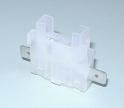
Automotive blade type fuses and fuse holders (pictured below) are excellent for this purpose as the fuses are easily accessible if they need changing, and it is clear if a fuse has blown. Blade fuses are available in many different sizes, each being a different colour.

In line automotive blade fuse holder

50A inline blade fuse


http://www.reuk.co.uk/Fuse-and-Solar-Panels.htm